It has been a while since I updated, but that is mostly because there has been a good bit of non-visible work completed. As we moved the project forward, there were two major workstreams towards a “finished shell.” But those streams have a common component:
- Getting the windows removed/realigned and prepared for exterior panels.
- Getting the subfloor installed.
The common component is that they both require welding. So, my thinking was that we could work both streams towards doing all the welding at the same time.
Windows
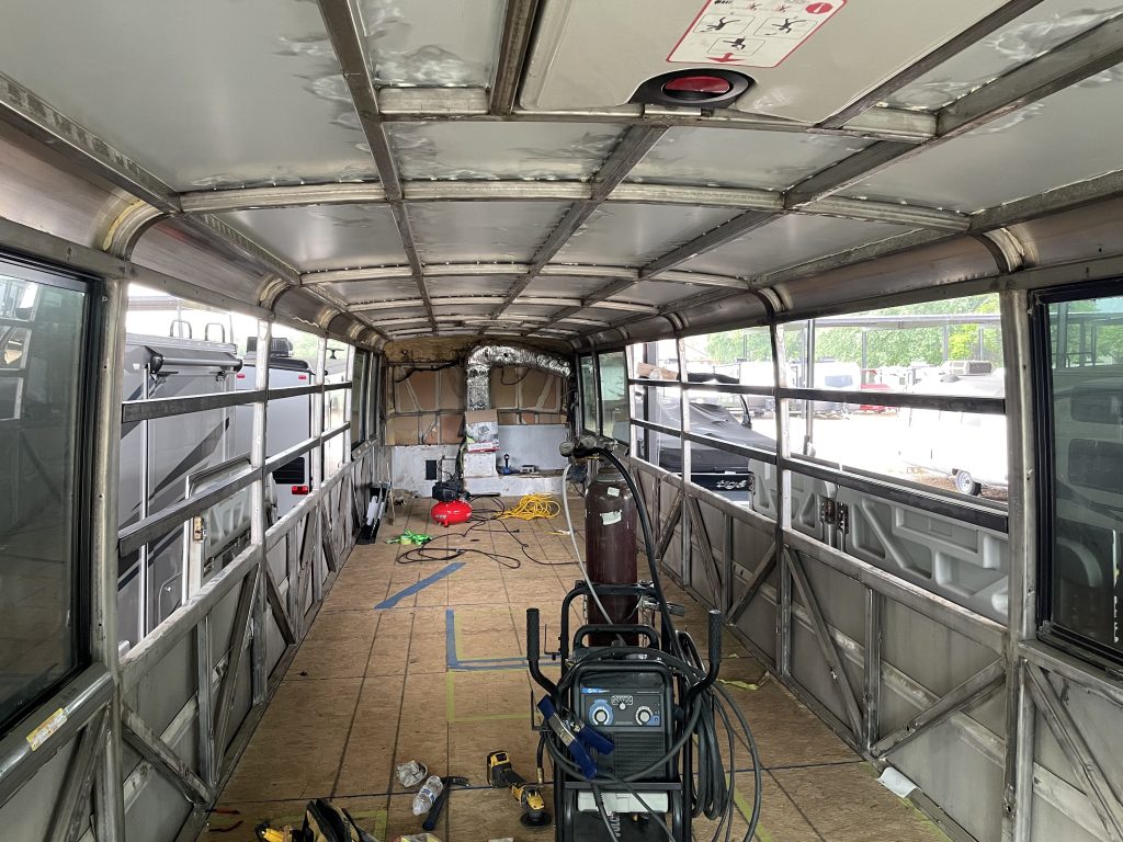
We started by temporarily laying most of the subfloor sheets in place so we could map out the floorplan in real space. I used various colors of tape to mark out the plan. This allowed my wife and I to walk through the space and make sure we were more or less OK with the general spacing. Is there room to move around the bed? Are the walkways wide enough. Does this make sense for where we want a door?
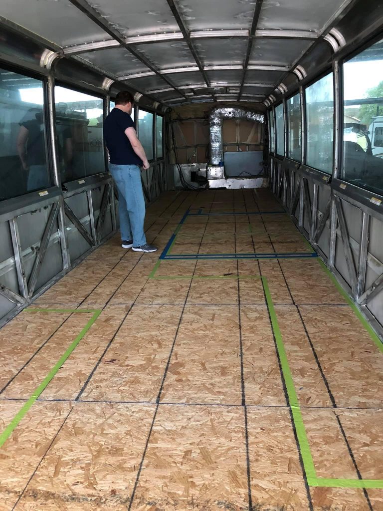
The ultimate goal was to be comfortable with where we did and did not need windows. I made the decision early on that, because the J4500 windows are double-paned and tinted, there was really no need to replace them with normal RV windows, which saves a ton of work and $$$, plus you get pretty expansive windows. I also think RV windows would really take away from the beautiful external lines of the J4500.
There are a few tradeoffs with that approach. First, the windows might not exactly line up to what you want. One of the items my wife wanted was a window over the kitchen sink. I can do that with the original windows, but they are not counter-height. So, where the counter extends into the window space, I’m going to have to figure out some creative solution for back side of where the cabinet/countertop extend over the window. However, it is only a couple feet, so even if I just have to black out the back side of the cabinet, it’s not a big deal. But I am mulling some alternatives…
The second tradeoff is that RV windows are generally designed to slide open and have screens, so that you can open them and get external air, breezes, etc. The factory windows of the J4500, not so much. However, the original MCI designers actually helped me on this one.
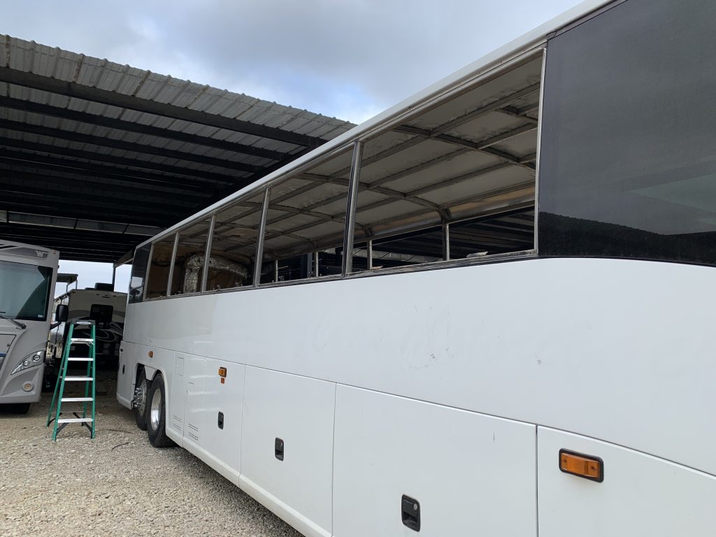
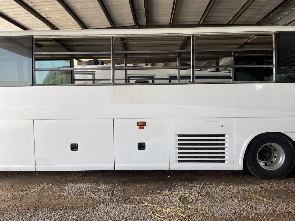
Once we had decided that the floor plan was good, it became apparent that the middle three windows on the driver’s side had to go, and one of the middle three on the passengers side (the front one of the middle three) had to go. The other two middle windows on the passenger side didn’t necessarily have to go, but they didn’t serve any purpose either. They were just along the hallway, where no one was going to really spend any time looking out them. However, they would reduce the energy efficiency of the overall shell.
So, I decided that it just made sense to take out the middle three windows on each side. The big downside to that is the middle three windows on each side are the emergency exit windows. So, I would only have the roof emergency exits remaining, which is not optimal.
However, in their quest for efficiency, the MCI engineers decided to make the emergency exit windows and the non-emergency exit windows the same size (except for the first and last windows on each side.) In fact, the windows are the same. The difference is the latch hardware vs. the mount hardware on the window and in the bus frame.
That means that I can move the emergency exit windows “outwards” (from the middle) one space and still retain 4 emergency exit windows (2 per side). I just need to add the latch hardware to the frame. I ended up just keeping three of them because keeping the latch mechanism where the cabinet comes in front of the one window was problematic. With a cabinet in place, there would be no room to pivot the latch bar to open the window. So, we have one emergency exit window on the driver’s side and two on the passenger side (plus the two roof exits.)
We can make rollable (for storage) screens that will attach to the window frame with magnets. So, we can still prop open the windows if we want to.
Now that I had decided what I wanted to do, I had to figure out the mechanics. The MCI engineers really impressed me with their simplicity. Essentially, the vertical attachment of the window is done by gravity. (The horizontal attachment is just the latch mechanism.) The bottom edge of the drip rail is a “J” channel looping back towards the bus. The top edge of the window is the same looping the opposite direction. The key is that the “J” is sharply curled so the window must be at almost at a 90 degree angle to the body of the bus to get hooked onto or removed from the drip rail. In addition to the mounting, this also provides the hinge mechanism for the emergency exit windows. To prevent the windows from swinging far enough to dislodge from the drip rail after installation they just attach small clips to the corner of each window frame right up against the drip rail.
The simplicity is great, but that gets tempered when you realize that removing/installing the windows requires them to be lifted up to (or down from) 13+ feet and to the 90 degree point (flat out from the bus.) Did I mention that the windows are HEAVY? With the help of my sons, we were able to remove the windows. But, that took everything we had. There was no way we could “brute force” getting the emergency exit windows back into the new locations.
After some thinking, I realized that a sheetrock lift for ceilings might do the trick. So, I rented one for a few hours and it made quick work of re-installation. All ended well, but it dawned on me a couple weeks later that I had drastically overthought the problem. Because of how they mount to the drip rails, I could just have removed the windows I didn’t want and slid the emergency exit windows from the prior locations into the new locations. (Duh…)
Mechanical
The other thing I wanted to do before we put the sub-floor in was to address any mechanical needs that could be easier done without the floor in place. For example, all the air lines for the brakes and air bags are more easily accessible without the floor in place. You could address any issues with those after the floor is in place, but it is much easier without it.
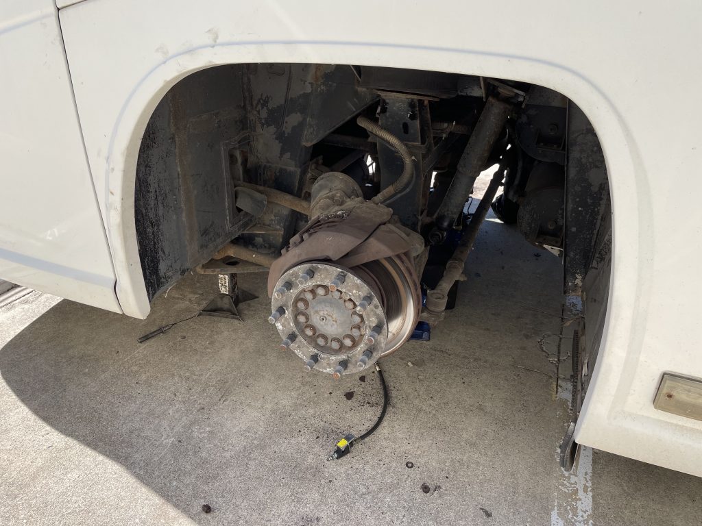
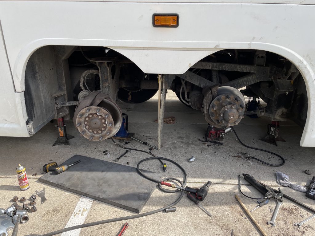
So, I asked my “MCI guy” to inspect all of that for anything we needed to address. We then took that list and realized doing those things would require blocking up the coach and removing the wheels as well. So, I figured we should also address anything else in the “wheel well” area at the same time.
That lead to sourcing air bags, shocks, brake pads, some bushings, a v-link, air dryer, air tank drains, and the occasional air valve. Of course, MCI (NFI Parts) is VERY proud of their parts. However, most of the parts are not unique to MCI. So, the key is finding the OEM part numbers (which NFI will NOT share) so you can find the parts elsewhere. Many companies have cross-references, but it took a good deal of research. Once I had the OEM part numbers, I could source parts from a wide variety of companies; truck parts companies, manufacturers, even Prevost (They LOVE to undercut NFI Parts prices.) On the whole, I saved around 50% from what I would have paid if I sourced from NFI.
Once the parts all arrived, I got my first experience of blocking up the bus and climbing around under it.
Welding
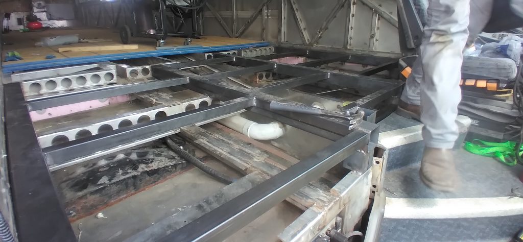
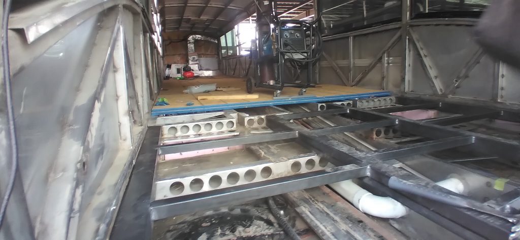
As I contemplated the sub-floor, there was one big job. The first rows of seating on a J4500 are “stadium” seating, which means that the floor steps down where the seats were and has a ramp down in the aisle space. For our purposes, the floor needs to be flat all the way forward. So, that “missing” sub-structure needed to be added. There were also a couple small places along each side where there is no structure to attach the floor (where vents used to be in the seated coach.) I decided I wanted to stick with what the manufacturer did, so the plan was to weld in stainless steel.
We also needed to put structure where we took the windows out so there is some framing to attach the body panel.
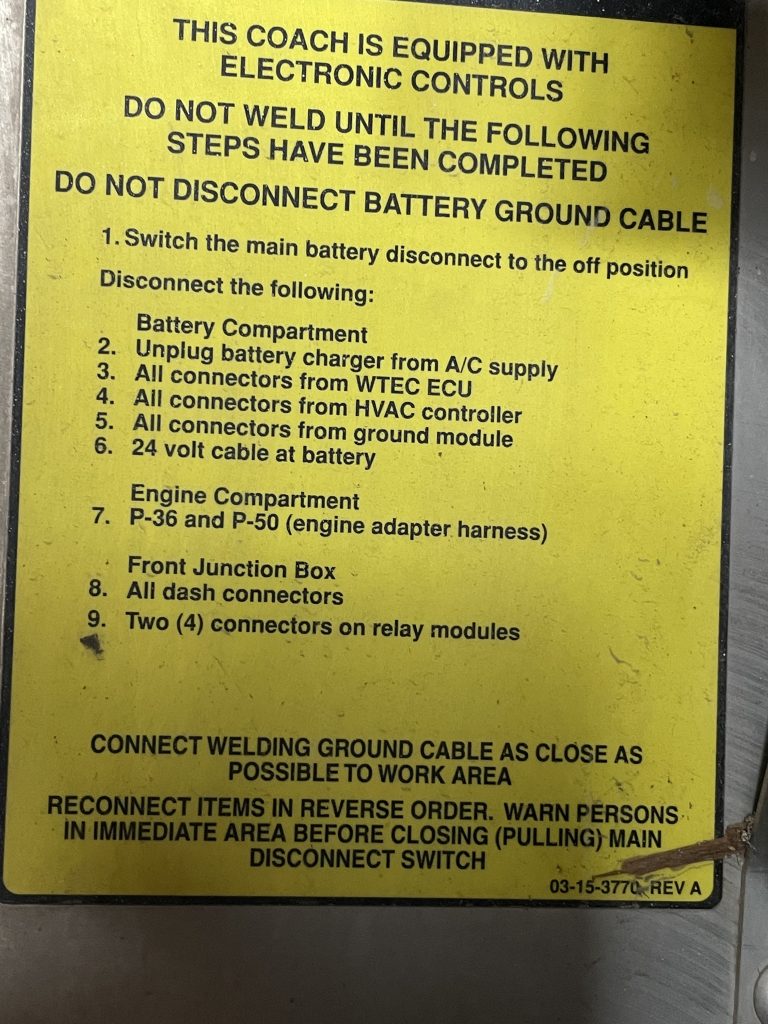
So, with the windows moved and the mechanicals completed, we were now ready to move on to the welding. Well, not really… Given all the electronics in these coaches, there is a set of tasks which need to be completed BEFORE welding to make sure you don’t let the smoke out of any of the electronics.
That done, NOW we could do the welding…
What’s next
With the welding complete, the last step to a “finished shell” is putting body panels (blanks) where the windows used to be. There are some considerations for this.
- Materials – The options (generally) are sheet metal (aluminum or stainless) or fiberglass (FRP). I’m strongly leaning towards fiberglass for consistency as the rest of the exterior is fiberglass. Metals also introduce other issues in installation, insulation, etc.
- Mounting – Believe it or not, the existing exterior fiberglass side panels are glued on. MCI uses Sikaflex to attach the body panel to aluminum rails. So, I suspect we will do the same thing. There are no existing rivets on the exterior, so I don’t want to add any, for aesthetic reasons.
- DIY or not – I know I can source all the materials to do it myself. However, there are two considerations that concern me. First, if it is not done properly, large fiberglass panels come flying off the bus as we go down the highway. While not an immediate concern to those inside the bus, I suspect other drivers around me would be fairly unhappy. Second, the frame and windows of the bus are not flat. They gently curve from the drip rail to the existing body line. So, in the installation process, I would have to hold the fiberglass to the curved frame while the glue sets. This has to be done via some kind of structure applying pressure from the outside for a period of hours. I don’t really have a way to do that like a large body shop would. (There are a couple truck/RV body shops locally.) The only way I could think to do it would be to temporarily rivet the panels in place and then remove the rivets and fill the holes, which I’m not sure I want to do. So, I will price doing it myself or having a shop do it and see what makes sense…
Updates to the floorplan…
I have made some minor updates to the floorplan. First, I have added dimensioning showing how the bays align to the interior as well as where the under-floor tunnels run. This helps make sure my plans for where to put specific things aligns to access points and equipment in the bays.
This led to the realization that the original toilet location would have been too far away from the black tank, mandating a much more expensive toilet. While we have not decided on what toilet we are going to use, I didn’t want to be boxed into that limitation. So, I pivoted the alignment of the shower and the toilet. This actually makes the shower a hair longer, but loses an inch or so of ceiling height from one end of the shower, due to the curved roof, but I think we will still be fine. It also creates a void space where the sink cabinet and shower meet. I will have to get creative to make good use of that space.

Good progress! But where are the kids going to sleep?
My kids are all adults, so they can sleep in tents… Actually, the couch will jack knife into a double bed and there will be room for a twin air mattress in the kitchen if really needed.
Excellent article I have read re: Hwy. Bus conversion – Motorhome.
Easy to understand, just enough details for the handy man.
Much appreciate you posting.
I’m a fan! Your articles and pictures are a huge help as I am designing my planned conversion of a J4500. Thanks!
I do have a question, and a favor, to ask. Could you tell me what is the measurement from the floor to the center of the ceiling? I can’t seem to find that dimension anywhere online.
Also, I am a cabinetmaker and so I noticed your comment regarding the countertop height being higher than the bottom of the window. I am planning on pulling the cabinets away from the window about 1-1/2″ and having the countertop extend down to below the window, and then return below the window. This gives room for shades or blinds. The tops will be out of acrylic (Corian) so it is easy to make this look like one continuous top, and build in a small lip at the back so things don’t roll off the backside of the cabinet.
Thanks in advance, and I look forward to your next progress post.
The height from the floor frame to the roof frame is 79.5″ so your choice of subfloor, flooring, insulation, ceiling material, etc. will subtract from that.